|
|||
MIL 3, Inc.
OPNET is a registered
|
University: Northeastern University, Boston, MA Professor: John G. Proakis Department: Electrical and Computer Engineering Design and Simulation of an Underwater Acoustic Local Area Network With the advances in acoustic modem technology that enabled high data rates and thus reliable communications, current research focuses on communication between various remote instruments within a network environment. Underwater acoustic (UWA) networks are generally formed by acoustically-connected ocean-bottom sensors, autonomous underwater vehicles (AUVs) and a surface station, which provides a link to an on-shore control center. While many applications require long-term monitoring of the deployment area, the battery-powered network nodes limit the lifetime of UWA networks. In addition, shallow water acoustic channel characteristics, such as low available bandwidth, a highly varied multipath and large propagation delays, restrict the efficiency of UWA networks. Within such an environment, designing an UWA network that maximizes throughput and reliability while minimizing the power consumption is a very difficult task. The network consists of two types of nodes: 1) Sensor Nodes: These nodes collect data using their sensors. The collected data is then passed to the master nodes through the network. There may be as many sensor nodes as needed depending on the area to be covered. 2) Master Nodes: Master
nodes are responsible for collecting data from sensor nodes. The collected
data is then passed to a gateway node that connects the acoustic network
to the user on shore. In this simulation, we don't include gateway connection.
Master nodes can also issue commands to control sensor nodes.
The sensor nodes are
connected to the master node in a hierarchical manner. The number of hops
that is required for a sensor node to communicate with the master node
determines the level of the node.
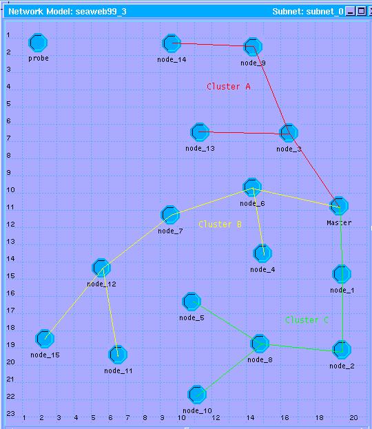
The available frequency band is divided into sub-bands and each sub-band is assigned to a cluster of nodes. A cluster of nodes is deployed in the same general geographical region. The neighboring clusters are assigned different frequency bands to assure low interference. Each cluster communicates with the master node through its first level node. Figure shows the network topology created using the network editor of Opnet. The network consists of a single master node and fifteen sensor nodes. Sensor nodes are divided into three clusters. Master node uses frequency group M. Sensor nodes are assigned frequency groups A, B, and C, as shown in the figure. The lines connecting the nodes represent the virtual communication paths created by the acoustic modems. The details of this work can be found in the following papers:
|