


Lab 3 Introduction
Once the behavior of a system has been determined (such as using an FSM model), it may need to communicate to other devices or to the real world. In this lab we build the foundation for both, using RS232 and an interface board used to communicate with a breadboard prototype.
You may want to read Chapter 13 in the BF561 Hardware reference manual. The VDSP++ IDDE has a good example of UART communication and is discussed below.
Examine the UART Terminal Example
Using the UART Terminal example located at C:\Program Files\Analog Devices\VisualDSP 4.0\Blackfin\EZ-KITs\ADSP-BF561\Examples\UART RS-232 HyperTerminal session, determine which registers are being used in the example - and how and why they are used. Determine what happens step-by-step with RS232 using the FSM code you wrote.
Building the "Washing Machine"
Get a breadboard, LEDs, resistors, wires, and a DIP switch from the TA. You will build a simple circuit that takes as input VCC, GND, 5 wires used as output to the washing machine (inputs to the controller), and 3 wires used as inputs to the washing machin e (ouptputs from the controller). You can use the VCC and ground wires to debug.
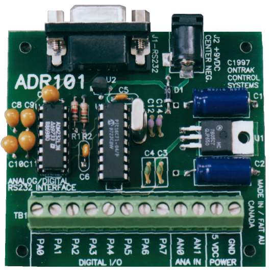
Interfacing with the ADR101
You can read more abot the ADR101's command syntax in the manual. Using these commands, rewrite the code to read inputs and write outputs with the following connecti ons.
- PA0 - load size knob (0 small, 1 large)
- PA1 - bottom water-level sensor (0 no water, 1 water)
- PA2 - middle water-level sensor (0 no water, 1 water)
- PA3 - top water-level sensor (0 no water, 1 water)
- PA4 - door sensor (0 open, 1 closed)
- PA5 - water drain valve (1 opens, 0 closes)
- PA6 - agitation motor (0 off, 1 on)
- PA7 - water supply valve (1 opens, 0 closes)
Finally, we'll interface the Blackfin 561 board with the ADR101. We will use the TA's PC with Hyper Terminal as a communication arbiter between the BF561 controller code you wrote, the ADR101 RS232 data acquisition device, and the washing machine prototype you built.
Building the "Washing Machine"
Get a breadboard, LEDs, resistors, wires, and a DIP switch from the TA. You will build a simple circuit that takes as input VCC, GND, 5 wires used as output to the washing machine (inputs to the controller), and 3 wires used as inputs to the washing machin e (ouptputs from the controller). You can use the VCC and ground wires to debug.
Connect two BF561s
If time permits, connect two BF561 boards and develop a program that utilizes RS232 I/O in the control flow of a program.
Resources
You may want to read about RS232 connections.