


Lab 5 Introduction
A digital image can be considered simply a vector (or "an array of values") with each element representing a value from which some information about the picture can be interpreted (that is, a picture element or pixel).
Whenever computer scientists or
engineers come across a number like 111, they know its value
(and hence its interpretation) depends upon the numerical representation
being used. It could represent the numbers "one hundred eleven," "seven",
"two hundred seventy-three," or even represent the sound of a bell. The
same is true of digital images and their representation formats.
So the data in an image is represented by a set of values:
![\[ \left \{ x_1,\ x_2,\ x_3,\ \dots \right \} \]](images/form_56.png) But because digital images often depict 2-dimensional data, we are
interested in representing the set of data in a matrix (i.e., with width
and height dimensions). Therefore, if we let
But because digital images often depict 2-dimensional data, we are
interested in representing the set of data in a matrix (i.e., with width
and height dimensions). Therefore, if we let
 denote the width and
  denote height, we have a matrix like:
![\[ \left [ \begin{array}{ccccc} x_1 & x_2 & x_3 & \dots & x_{1w} \\ x_{w+1} & x_{w+2} & x_{w+3} & \dots & x_{2w} \\ x_{2w+1} & x_{2w+2} & x_{2w+3} & \dots & x_{3w} \\ \vdots & \vdots & \vdots & \ddots & \vdots \\ x_{(h-1)w+1} & x_{(h-1)w+2} & x_{(h-1)w+3} & \dots & x_{height \times w} \\ \end{array} \right ] \]](images/form_75.png)
Side note: not all data represents two dimentions. Adding time to width and height data can be interpreted as moving images (i.e., video) and hyper-spectral satellite data or multi-dimensional medical data exist for 4-dimensional data (such as three dimensions in time). But many multi-dimensional data sets can be effectively analyzed two dimensions at a time.
One popular image representation format is RGB shown in Table 1: where the red, green, and blue values of a pixel are represented. RGB24 is a format where each of the three colors is 8-bit (i.e., are valued from 0 to 255).
| Red | Green | Blue |
| 8-bit | 8-bit | 8-bit |
Let's assume we are interested in the RGB values of the a pixel represented
by
 ,
where
,
where 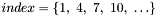 .
Note that in the matrix above,
.
Note that in the matrix above,
 (because there are three values to every RGB pixel).
Let's examine the indexing of the bottom line where  is the form. Since
  , the index of
  can be recast as
  .
.
To develop a generic image processing algorithm, we might need to process every RGB pixel in an image. Therefore we can use the indexing form above for a generic algorithm.


![$5\ \ \ \ \ \ \ \ \ \ [\ \texttt{perform processing}\ ] $](images/form_95.png)

Reading an Image
A natural place to start is to simply read in an image file and view it using the VDSP++ Image Viewer.
Your program will read in the file img.rgb24
where each line in the file represents a pixel's red, green and blue values -- separated by commas.
Each 8-bit value represents the RGB values - respectively (from 0-255, so black is 0,0,0 and white is 255,255,255). Since there are three 8-bit values,
the format is referred to as RGB24.
A few example lines from the file are as follows:
153,51,51
204,51,51
204,102,102
204,204,204
255,255,204
255,255,255
Your code will need to convert the RGB24 value to RGB565 (a format where
16 bits are used to represent the pixel, rather than 24 bits). (You can
read more about the RGB colorspace at this Wikipedia page).
You may want to use the #define macro from this page:
#define RGB565(r, g, b) ((r >> 3) << 11)| ((g >> 2) << 5)| ((b >> 3) << 0)
A good way to represent these color elements is with a struct:
typedef struct  {
	// 2-byte 0-65,535 color values
	unsigned short red;
	unsigned short green;
	unsigned short blue;
} RGB24_t;
Once you have VDSP++ running and a new project started, click on
View -> Debug Windows -> Image Viewer
You should see the dialog box in Figure 1. Select the RGB565 Pixel Format under Image Info and whatever you used for the Width and Height.

You should have a VDSP++ session similar to the one in Figure 2, with the Image Viewer window at the top right.

We need to configure the Image Viewer to look for a specific memory space in your program. In order to do this, use the following in your main C program:
volatile unsigned short ImageData[ARRAY_SIZE];
and this in your main header file:
extern volatile unsigned short ImageData[ARRAY_SIZE];
The ARRAY_SIZE macro will of course have to be defined.
When different images are used, both the array size and the
configuration of Image Viewer will change. The ImageData array is
where we will keep our image data, so write the code to read in the
RGB24 image file, convert the values to RGB565, and save the data in the
appropriate ImageData element.
Once you have the code written for reading the image data into the ImageData array, and built the Project, Right-click on the Image Viewer subwindow and
select Configure. You will again see a dialog similar to Figure 1. This time select the Start Address button that says "..." -- select the Symbol entitled "ImageData" and click OK. (You can also select the checkbox Option for Update on Halt, but be careful to allow your program to fully halt when you use this.) Run your program to see the what image the file represents. Because of the data
being transferred this may take some time. Once your program is done, click on
the refresh icon (two arrows) in the Image Viewer.
Part Two: Image Processing
Using some image data, read in the data, convert it, and do a simple processing routine. A high-pass or low-pass filter is simple, where pixels that are below and above certain thresholds are colored black, whereas pixels that are above and below those thresholds as "passed" through the filter and their colors are retained.
As another example, build a fire-detection video filter. That is, determine the colorspace that ``fire'' occupies, filter out (blacken) pixels in the image that do not lie within that colorspace, and pass the pixels that do. A good threshold for the fire colorspace is about 60,000 - i.e., RGB565 pixels below 60000 should filtered out.
Figures 3 and 4 show an image mde from a single frame of video before and after filtering.
|
Figure 3. Image before filter

|
Figure 4. Image after filter

|
Figures 5 and 6 show the whole video (i.e., sequence of images, each on processed just as the frame in Figure 3).
|
Figure 5. Video Dataset
|
Figure 6. Processed Data
|